


Request a quote and receive a price in about 15 minutes.


Quick Quotes
Fast Shipping
1 Year Warranty
EMS 40-125-2-D Technical Specifications:
| Manufacturer | TDK-Lambda |
|---|---|
| Model | EMS 40-125-2-D |
| Type | DC Power Supply |
EMS 40-125-2-D
Home EMS 40-125-2-D
| Part Number | EMS 40-125-2-D |
| Manufacturer/Brand | TDK Lambda |
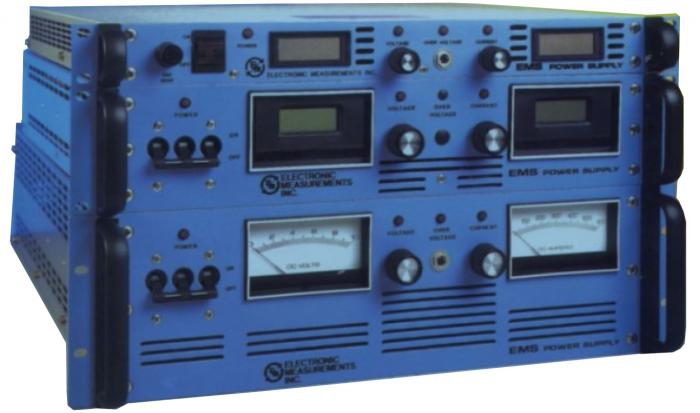
| Description | EMS DC Power Supply 0-40V@ 0-125A Digital Regulated |

In Stock | Ships Today
Speak to a sales representative for pricing & lead time:
 Phone:
1-919-809-5227

• Quick Quotes: Receive Price & Availability Today!
• Warranty: 1 Year Warranty Covered by Apex Waves
• Calibration: Ask About Our Tiered Calibration Levels
• Option & Modules: Confirm Your Requirements or Versions
• Repair: Cost & Lead Time Available Upon Request for Service
- Description
- Technical Specifications
TDK Lambda EMS 40-125-2-D Power Supply
In the TDK Lambda EMS 40-125-2-D Power Supply, with an estimation of the essential current of the transformer and the current of the breaker, the unit can be monitored by the current transformer (s) in the inverter Bd. The signal is amended and filtered, producing an unregulated DC voltage that is utilized for maximum current limiting. The amended voltage of the inverter may be fed to the inverting terminal of a comparator and it will be contrasted to a reference that is attenuated from 5 Vdc of the PWM. The reference may be established by means of a potentiometer. This circuit is triggered when the switch current in the inverter surpasses 22 amps, as accomplished in fault conditions as the saturation of the power transformer or short in the inverter pins 5 and 8 (Pin 9 for 1KW).
The EMS 40-125-2-D includes a Set-Point Reference; the separate constant current sources offer reference voltages for the voltage and current channels. The collector current of Q1 drives the voltage control potentiometer that is spotted on the front panel, whereas Q2 drives the current control potentiometer. The positive bias voltage supply is RC filtered with R8 and C10 to decrease noise feedthrough. The current sources are referenced by the voltage across CR5, a temperature remunerated zener diode. The current from each of the sources may be adjustable to 1 mA to R3 and R5.
If you are interested in this model and you want to learn more about its options, specifications, and features, you can check its manual, which is available on the ApexWaves.com website.
| Model | EMS 40-125-2-D |
|---|---|
| Manufacturer | TDK Lambda |
| Series | EMS |
| Type | DC Power Supply |
| Output Voltage | 40 V |
| Output Current | 125 A |
| Frequency | 47-63 Hz |
| Warranty | 2-3 Year Warranty |
| EMS 40-125-2-D Manual | User Manual and Maintenance Manual Available for Download |
| Price | Contact a sales representative for a quote. |
EMS 40-125-2-D
Main Image
Secondary Image
EMS DC Power Supply 0-40V@ 0-125A Digital Regulated
In Stock
Ships Today
919 809 5227

Rated 0/5 based on 0 ratings.
- EMS 40-125-2-D Technical Specifications
| Manufacturer: | TDK-Lambda |
|---|---|
| Model: | EMS 40-125-2-D |
| Type: | DC Power Supply |